Specification
Type
Clamp / operating handle
Steel
Bearing flange
Sheet steel, blackened
Spindle assembly
Steel, blackened
Counter plate / bearing pin
Steel, blackened
Information
GN 855 C-clamps feature an especially robust, sturdy and compact design, allowing them to be used under severe and demanding conditions, e.g. higher temperatures, dust, mist, etc.
The C-clamps are normally installed and mounted at the clamping point. The counter plate (supplied loose) has a ball socket and is designed for attaching to the counter piece to be clamped. In connection with the ball-type bolt, this configuration ensures the precise positioning of the latch clamp.
If the counter plate is not to remain at the counter piece to be clamped, the clamping bracket may alternatively also be used to hold GN 802- toggle clamp spindle assemblies which have a pendulum-type bearing surface.
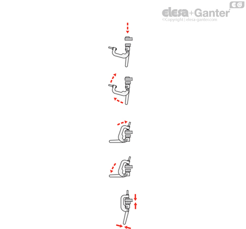
Description of function
Place the pieces to be clamped into the clamping position, e.g. close the lid or place the piece to be clamped on top.
Then move the clamping bracket and the operating handle of the C-clamp upwards.
Now move the clamping bracket forward such that the clamping bolt is located in the ball socket of the counter plate.
Move the operating handle downwards until the clamping force has exceeded the dead point.
When closed, the C-clamp now holds its position on its own.