Izvedba
Oblika
Type E: with rubber stop, locking device in back
Številska oznaka
No. 2: Fastening using countersunk holes
Profil vodila
Steel, zinc plated, blue passivated ZB
Krogle
Kotalni ležaji, kaljeno jeklo
Kletka krogle
Jeklo, pocinkano
Gumijasti omejilnik
Plastic / Elastomer
Operating temperature -20 °C to 100 °C
Informacije
Telescopic slides GN 1420 are installed vertically and in pairs. The stroke reaches ≈ 100 % of the nominal length l1 (full extension). The rubber stops of type E dampen the impact of the slide in the two end positions and takes on the locking function of the back stop position. This feature is noticeable through a slight resistance on opening and closing. If larger static or dynamic loads occur in the direction of extension, they should be absorbed by external stop elements.
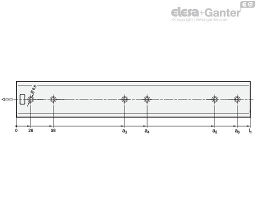
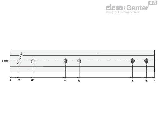
The telescopic slides are delivered in pairs. They can be installed on the extension on either the left or right side due to the mechanics. Dostopnost vseh montažnih izvrtin je zagotovljena s pomožnimi izvrtinami. Prisotne so lahko tudi druge proizvodne izvrtine, vendar so prikazane le montažne izvrtine.
Montažne izvrtine
Montažne izvrtine – zunanje vodilo
| l1 | a3 | a4 | a5 | a6 |
| 250 | 168 | 200 | - | - |
| 300 | 218 | 250 | - | - |
| 350 | 250 | 282 | - | - |
| 400 | 186 | 218 | 314 | 346 |
| 450 | 218 | 250 | 378 | 410 |
| 500 | 218 | 250 | 410 | 442 |
| 550 | 282 | 314 | 474 | 506 |
| 600 | 282 | 314 | 506 | 538 |
| 650 | 314 | 346 | 570 | 602 |
| 700 | 314 | 346 | 605 | 634 |
| 750 | 346 | 378 | 666 | 698 |
| 800 | 378 | 410 | 698 | 730 |
Montažne izvrtine – notranje vodilo
| l1 | i3 | i4 | i5 | i6 |
| 250 | 168 | 200 | - | - |
| 300 | 218 | 250 | - | - |
| 350 | 250 | 282 | - | - |
| 400 | 154 | 186 | 314 | 346 |
| 450 | 154 | 186 | 378 | 410 |
| 500 | 186 | 218 | 410 | 442 |
| 550 | 250 | 282 | 474 | 506 |
| 600 | 250 | 282 | 506 | 538 |
| 650 | 282 | 314 | 570 | 602 |
| 700 | 314 | 346 | 602 | 634 |
| 750 | 346 | 378 | 666 | 698 |
| 800 | 346 | 378 | 698 | 730 |
Pritrdilni vijaki
For the said loading forces FS to be absorbed reliably in the surrounding structure, all available countersunk holes of the outer and inner slide must be used. Failure to use fastening screws reduces the specified load capacity accordingly. The following screws can be used for mounting:
| Designation - standard | Outer slide | Inner slide |
| Hex socket countersunk head screw DIN 7991 | M 5 | M 5 |
| Countersunk screw, Phillips DIN 965 | M 5 | M 5 |
| Countersunk screw, Phillips DIN 7997 | Size 5 | Size 5 |