Specification
Coding
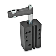
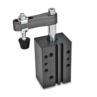
Types
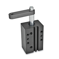
- Type A: Clamping arm with slotted hole and 2 flanged washers
- Type AC: Clamping arm with slotted hole, 2 flanged washers and spindle assembly
- Type B: Clamping arm with threaded hole
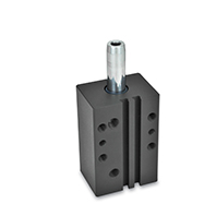
- Type N: Without clamping arm
Aluminij
Hard anodized
Wear-resistant surface
Double-action air cylinder
Max. pressure 6 bar
Socket cap screw DIN 912
Steel, zinc plated, blue passivated
Washer ISO 7092
Steel, zinc plated, blue passivated
- Steel, zinc plated, blue passivated
- Rubber thrust pad 85 Shore A
Information
Swing clamps GN 875 are used when the clamping point for inserting and removing the workpiece must be freely accessible on top.
During the clamping action, the arm is first swiveled by 90° and lowered, followed by the linear tensioning motion. The workpiece clamping must take place within the clamping stroke.
The angle orientation of the tensioning arm can be set arbitrarily during mounting on the swing clamp. When tightening the screw, the piston rod must not experience any torque. The clamping arm must therefore be held to prevent twisting.
The swing clamps are equipped with a magnet ring piston and are therefore pre-fitted for end stop detection via sensor.
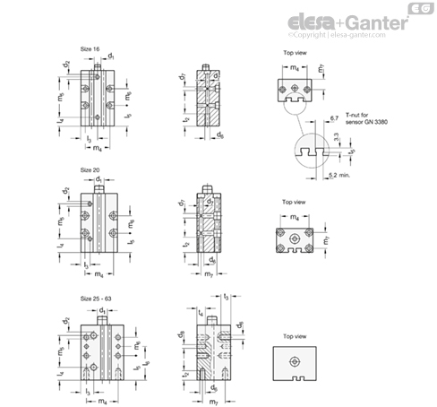
Fastening and mounting dimensions
| Size | d1 | d6 | d7 | d8 H7 | l3 | l4 | l5 | l6 | m4 | m5 | m6 | m7 | t2 | t3 | t4 | t5 ≈ |
| 16 | M 5 | M 5 | 4.5 | - | 21 | 11 | 26 | - | 31 | 51 | 21 | 13 | 15 | - | - | 4.7 |
| 20 | M 6 | M 5 | 5.5 | - | 11.5 | 17 | 24 | - | 36 | 44.5 | 22 | 20 | 20 | - | - | 5 |
| 25 | M 8 | M 6 | - | 6 | 17 | 17 | 33 | 48 | 40 | 44.5 | 30 | 20 | 15 | 10 | 10 | 4.5 |
| 32 | M 8 | M 6 | - | 6 | 18 | 18 | 40 | 55 | 45 | 51 | 30 | 30 | 20 | 15 | 15 | 6 |
| 40 | M 8 | M 8 | - | 6 | 21 | 21 | 40 | 55 | 52 | 52 | 30 | 37 | 20 | 15 | 15 | 7.5 |
| 50 | M 10 | M 8 | - | 8 | 26 | 26 | 40 | 60 | 66 | 53 | 40 | 46 | 20 | 20 | 15 | 6 |
| 63 | M 10 | M 8 | - | 8 | 30 | 30 | 40 | 60 | 80 | 53 | 40 | 60 | 20 | 20 | 15 | 7.5 |